Features
● Low dependence of electrical and optical characteristics over temperature
● Data rates from OC-3 to OC-48
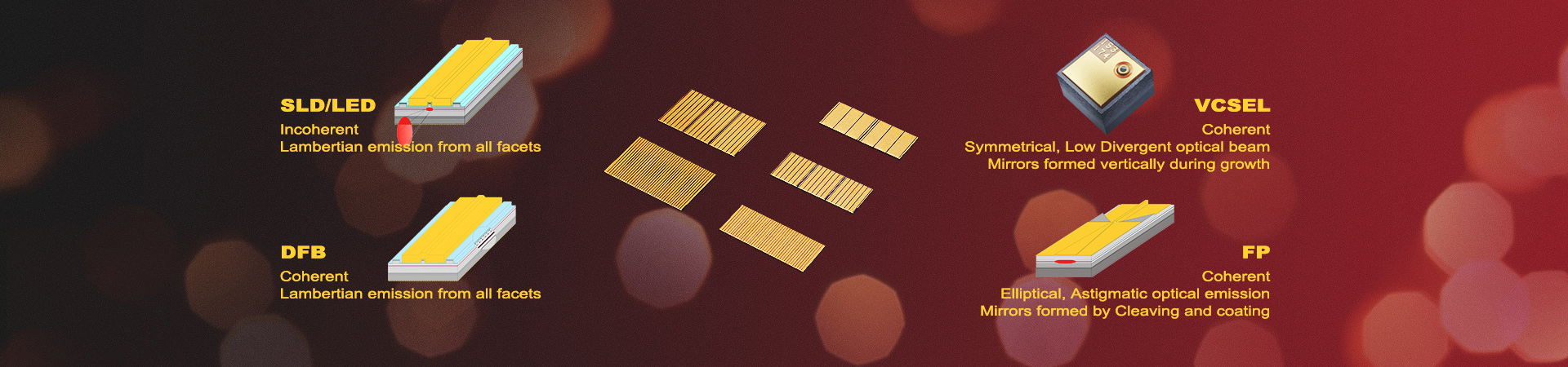
● Vertical Cavity Surface-Emitting Laser
● Internal TEC and Thermistor, ESD protection
● Narrow linewidth
● 2 nm tunability with TEC
E/O Characteristics
Condition:TO P = 20°C, IO P = 10.0 mA unless otherwise stated (TO P = chip backside temperature, controlled by the TEC)
Parameters | Symbol | Min | Typ | Max | Unit | Remark |
Emission Wavelength | λR | 850nm |
Threshold current | ITH |
| 1 |
| mA |
|
Output Power | Popt | 0.5 | 1 |
| mW |
|
Threshold Voltage | UTH |
| 1.8 |
| V |
|
Driving Current | IOP |
| 3 |
| mA | Popt = 0.5mW |
Laser voltage | UOP |
| 3 |
| V | Popt = 0.5 mW |
Electro optic conversion rate | ηWP |
| 12 |
| % | Popt = 0.5 mW |
Slope efficiency | ηS |
| 0.3 |
| W/A |
|
Rise and Fall time | Tr /Tf |
| 90/120 |
| Psec |
|
Differential series resistance | RS |
| 100 | 200 | Ω | Popt = 0.5 mW |
3dB bandwidth | ν3dB | 0.10 | 2.5 |
| GHz | Popt = 0.5 mW Due to ESD protection diode |
Relative intensity noise | RIN |
| -130 | -120 | dB/Hz | Popt = 0.3 mW @ 1 GHz |
Wavelength tuning over current |
|
| 0.6 |
| nm/mA |
|
Wavelength tuning over temperature |
|
| 0.06 |
| nm/K |
|
Thermal resistance (VCSEL chip) | Rthermal | 3 |
| 5 | K/mW |
|
Side mode supression |
| 35 |
|
| dB | I = 2 mA |
Beam divergence | θ | 10 |
| 25 | ° | Popt = 0.5mW, full width 1/e2 |
Spectral Width |
|
| 100 |
| MHz | Popt = 0.5 mW |
Tec Characteristics | Unit | Min | Typ | Max | Remark |
Tec Current | mA | -150(Heating) |
| +300(Cooling) | Proper Heart Sink Required |
NTC Thermistor Resistance | KΩ | 9.5 | 10.0 | 10.5 | T=25℃@10 KΩ |
NTC Thermistor Resistance | KΩ | 10/exp{3892-(1/289K-I/TOP)} |
With TEC Pin definition

Without TEC Pin definition

Spectrum

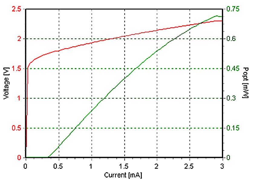
L-I Curve(T@25°C)
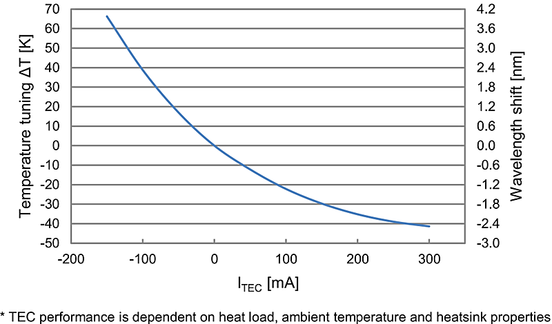
Temperature / wavelength tuning over TEC current*
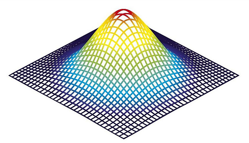
Beam Quality Profiler (2D/3D)
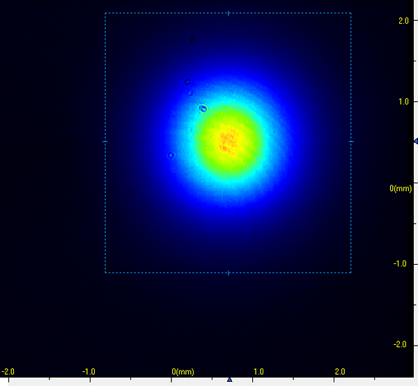
2D
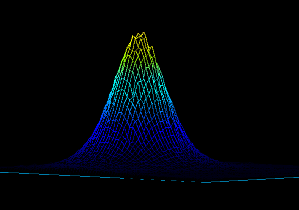
3D
Beam profile
In the far field, the intensity distribution of the single-mode VCSEL is perfectly Gaussian shaped
Package Size

Pin definition
TO package Bottom side View

Pin | Definitions | Pin | Definitions |
1 | TEC ( - ) | 5 | TEC ( + ) |
2 | THERMISTOR ( + ) | 6 | THERMISTOR |
3 | NA | 7 | NA |
4 | VCSEL Cathode | 8 | VCSEL anode |
Absolute Maximum Ratings
Item | Unit | Min | Typ | Max |
Store Temperature | ℃ | -40 | 25 | 125 |
Chip Temperature | ℃ | +10 | 25 | 40 |
Operating Current | mA | 0 | 3.0 | 5.0 |
Forward Voltage | V | 0.8 | 3.0 | 4.8 |
TEC Current | mA | -150 | - | +300 |
Soldering Temperature* | ℃ | 100 | 130 | 260 |
Electrical Power Dissipation | mw | - | - | 5 |
(*TEC temperature must be below 150°C)
Application
● Access network for long distance
● Local area network
● Gigabit Ethernet
Ordering Info
PL-VCSEL-□□□□-☆-A8▽-XX
□□□□:Wavelength
0760: 760nm
0850: 850nm
*****
1550:1550nm
☆ :TEC
0:Without TEC
1:With TEC
▽:Wavelength Tolerance
1:±0.5nm
2:±1.5nm
XX: Fiber and Connector Type
FS=Free Space
BFSA=Butterfly Package with HI780+ FC/APC
CPSA=Coaxial Package with HI780+ FC/APC
BFSP=Butterfly Package with HI780+ FC/PC
CPSP=Coaxial Package with HI780+ FC/PC
BFPP=PM Fiber+ FC/PC
PA=PM Fiber+ FC/APC