The PL-FP-1460-A-A81 -PA is 1460nm pump laser modules uses a number of revolutionary design steps and the very latest material technologies to significantly improve scalability of the production process. The semi-cooled 45°C laser diode operation provides for a significant reduction in TEC and overall power consumption. The module meets the stringent requirements of the telecommunications industry including Telcordia GR-468-CORE for hermetic 940 nm pump modules.
The LD-PD Series pump module, which uses Fiber Bragg grating stabilization to lock the emission wavelength, provides a noise-free, narrowband spectrum even under changes in temperature, drive current, and optical feedback. Wavelength selection is available for applications requiring the highest performance in spectrum control with the highest power available.
Electrical/Optical Characteristics (Tsub=25°C, CW bias unless stated otherwise)
Parameter | Symbol | Min | Typ | Max | Unit |
Centre Wavelength | λ | 1450 | 1460 | 1470 | nm |
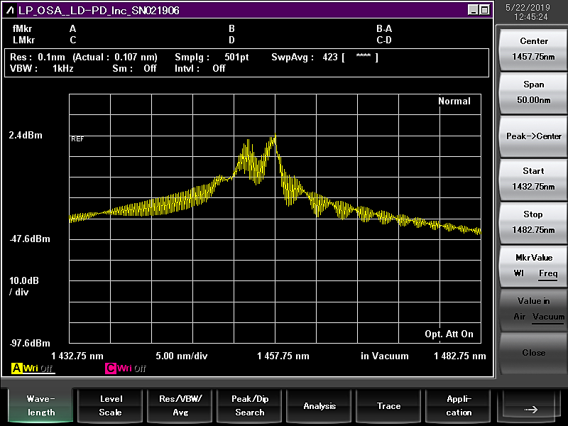
Spectral Width | Δλ | 1.0 | 2.0 | 3.0 | nm |
Threshold Current | Ith |
| 90 | 110 | mA |
Operating Current | Iop |
| 1200 | 1500 | mA |
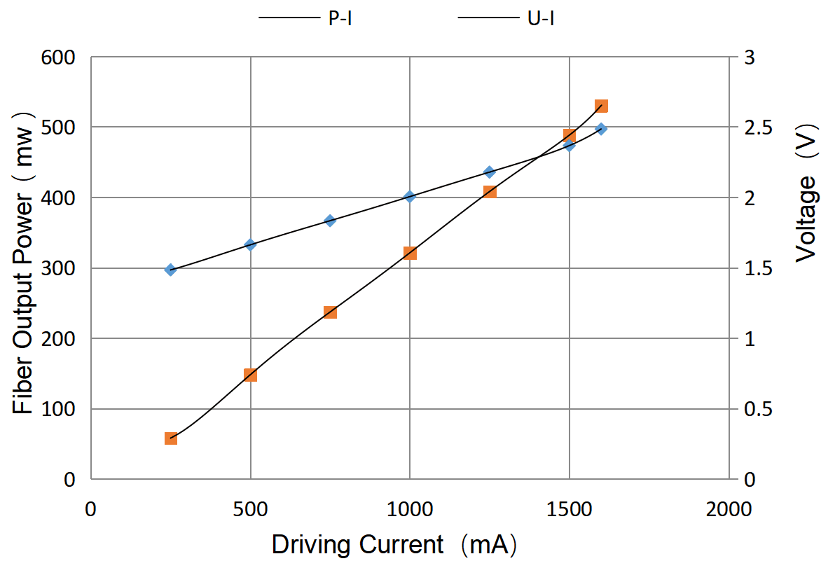
Fiber output Power | Pf | 300 | 400 | 650 | mW |
Wavelength Tuning VS Temp | Δλ/T |
|
| 0.01 | nm/°C |
Tracking Ratio(0.1Pop < Pf< Pop)1 | TR | 0.52 |
| 1.48 |
|
Tracking error2 | TE | -48 | - | +48 |
|
Monitor diode responsivity | IBF | 0.5 |
| 5 | uA/mW |
Thermistor resistance(Tset = 25°C)3 | Rth | 9.5 | - | 10.5 | KΩ |
PD Dark Current (VRD=5V) | Id |
|
| 0.1 | uA |
Extinction Ratio(PM VERSION) | PER | 17 | 20 |
| dB |
Coupled Fiber Type | SMF-28E |
Forward Voltage | Vf |
| 1.8 | 2.6 | V |
Thermistor Resistance | RT | 9.5 | 10 | 10.5 | KΩ |
Thermistor Temp. Coefficient |
|
| -4.4 |
| %/°C |
Connector | None or FC/APC |
Thermistor Resistance |
|
1. The tracking ratio is a measure of the front-to-back tracking when the output power is varied. On a plot of optical power versus back-face photocurrent, a straight line is drawn between the minimum power (30 mW) and the operating power (Pop) points. The tracking ratio is defined as the ratio between measured optical power (shown as data points on the plot) to the value derived from the straight line.
2. The tracking error is defined as the normalized change of output power relative to Pf at 25°C, that is, (Pf – Pf_25)/Pf_25, over case temperature range of 0 to 75°C, at constant back face monitor current corresponding to the lowest back face monitor current at Pf= Pop of 0°C, 25°C, 75°C.
3. Datasheet for Calculating Temperature from the resistance of the Thermistor is available now. You can contact us for details.
Spectrum
L-I Curve


 1460nm FP Raman Pump Laser Diode.pdf
