Physical/Optical Characteristics
Parameter
FEATURES | Min. | Max. | Unit | Note |
Power supply voltage | 4.8 | 6.1 | VDC | DC
A stabilized power supply is recommended |
Power |
| 10 | W |
|
Max drive current |
| 149/ 378/ 624 | mA | Jumper selection |
Current resolution(LSB) |
| Max Current/65536 | mA |
|
Current linearity |
| ±1 | LSB |
|
Current temperature drift |
| ±25 | ppm/℃ |
|
Current noise |
| 200 | pA/Hz1/2 | Built-in base source only |
Laser driving voltage |
| 3.4/2.8 | V | 5V power supply Half amplitude current/full amplitude current |
| 4.3/3.7 | V | 6V power supply Half amplitude current/full amplitude current |
Response frequency | 0 | 25 | MHz | -3db |
Temperature control range | -10 | 50 | oC |
|
Temperature resolution | 0.001 |
| oC |
|
Temperature stability |
| 0.002 | oC | Requires case cooling |
TEC output current | -1.5 | 1.5 | A |
|
TEC output voltage | -4.6 | +4.6 | V |
|
Analog input | 0 | 2.5 | V |
|
Installation Steps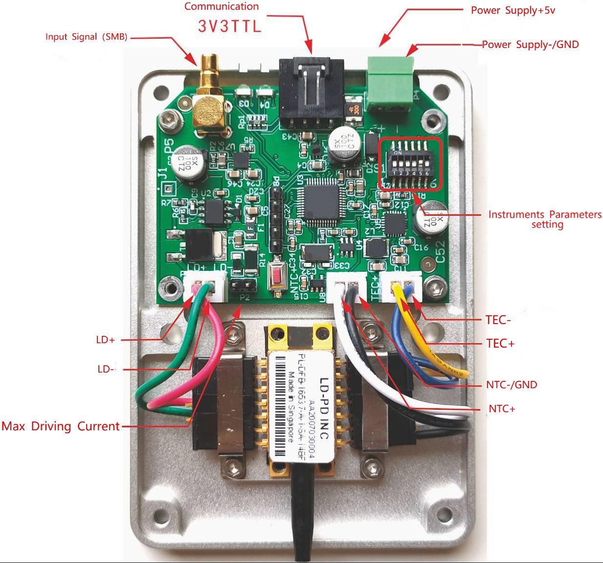

Please be sure to refer to the laser manual, the wiring sequence of the corresponding connector, and the wiring on the circuit board to confirm that the laser is compatible with the current wiring sequence. Powering on with an incorrect wiring sequence may cause damage to the laser!
The negative input of the module's power supply, the bottom plate and the negative pole of the NTC are all grounded. The positive and negative poles of the drive output are not grounded. When any functional pin of the laser to be installed is grounded (connected to its shell), special attention should be paid.
When there is a grounding situation of the laser function pin (such as the positive pole of the laser is grounded), a piece of sticky thermal conductive silicone needs to be placed between the laser and the bottom shell, and do not use metal screws to fix the laser to insulate the laser shell from the bottom shell. If you are not sure, please consult the engineer of the seller. Improper grounding will cause abnormal function of the module or even burn the laser!
Main Device Indicators
Jumper configuration
Before powering on, the module needs to adjust circuit parameters to suit the installed laser. Parameters are controlled by jumpers and DIP switches on the circuit board. Be sure to operate when the power is off!
Please set the maximum drive current of LDRVMLN to be equal to or slightly larger than the maximum allowable current of the laser. If the drive current is set too high, the risk of burning out the laser will increase.:

The P3 and P10 jumpers must be consistent, otherwise the instrument will not work properly! All operations should be performed with power off.
| Voltage select jumper |
Input voltage | 5V | Maximum driving operating voltage |
5V | Closure | 2.8V |
6V | Disconnect | 3.7V |
If the laser has its own voltage dividing resistor, try not to use this resistor.This will cause insufficient external drive voltage and put the laser in an under voltage state.
Panel

From left to right:
Power interface: 3.81mm connector, DC 5~6V, 3A. Use a low-ripple regulated power
supply to reduce overall system noise。
Communication interface: serial communication, baud rate 115200bps, 8 data bits, 1
stop bit, no parity bit; 3.3V TTL level. You can use a jumper to short-circuit the GND and
RX pins so that the system starts driving the laser according to the set internal current.
Please be sure to use this function after fully setting all parameters。
P+ and P- are auxiliary connection ports, and the internal connectors can be used to directly connect the laser pins.。
COM light: communication indicator light. When GND and RX are short-circuited, it displays red light.
SYS light: System status light. When the laser is not installed or the laser temperature has not stabilized to the set value, the yellow light is displayed. When the laser temperature has stabilized, the green light appears. When the internal drive current is turned on, a red light is displayed.
INPUT: SMB connector, input voltage 0~2.5V, input frequency 0~20MHz
Pay attention!
①Whenthelaser has a functional pin connected to the shell (such as a NEL laser,the positive pole is usually connected to the shell), the laser shell must be insulated
from the base: a layer of thermally conductive silicone pad is placed under the laser, and do not use metal screws to fix it.
②The laser current gear needs to be realized through short-circuit caps (jumper caps) on P3 and P10. A mismatch between the two will result in a mismatch between the system's self-recognition and the actual current, which may cause the laser to burn out!
③It is recommended to first connect an LED lamp bead or a cheap red laser to test whether the current setup is working properly.
④Laser temperature oscillation indicates that the temperature control PID parameters are set incorrectly. The temperature control parameter adjustment command is tecp kp kI kd. The effect will occur immediately after sending. Observe the temperature response accuracy and speed until satisfactory results are achieved. After the adjustment is completed, use the save command to save it.
⑤The module has no switch. After connecting the power supply, the temperature control function starts to work immediately, but the laser current source does not start. A green light indicates the temperature has stabilized. Use a jumper cap to short RX and GND to make the current source start working. Please use this function after the parameters are completely set!
External Signal Input
The signal input terminal INPUT on the rear panel of the instrument is used to receive external input. When the internal bias signal is not turned on, the equivalent circuit is as shown below:
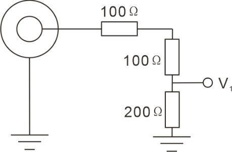
The driving current of the laser is:
ILaser = (V1/1.25V) x Imax
Imax=149mA or 378mA
When the internal signal is turned on, the equivalent circuit is as follows:
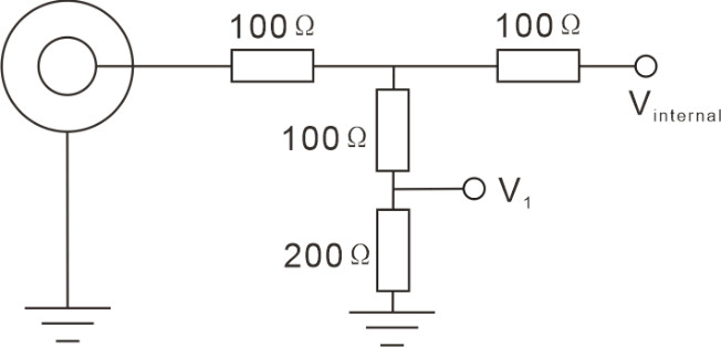
If only internal signals are used, all connections on the INPUT interface should be disconnected. If you want to use internal and external signals at the same time, please calculate the final effect by yourself according to the above equivalent circuit.
PC Control Interface
Replace the instrument cover, connect the controller to the power supply, and connect the computer with USB cable. Press power button ① to turn on the instrument. WIN7 and above system will prompt to install USB driver automatically. Please download the corresponding driver in http://www.ftdichip.com/Drivers/VCP.htm when using other systems or being unable to connect to the Internet. After the driver is installed, the virtual serial device will appear in the Device Manager.
Open the special software on the computer, as shown in the figure below:
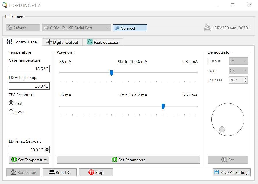
Find the corresponding virtual serial port in Communication Port, if not, click Refresh button. Click the Connect button, the console will light up after normal handshake, and read the current set value of the controller. Enter the required working temperature at LD Temp Setpoint, and click Set Temperature setting. Start slider bar sets the constant working current value, and Limit slider bar sets the maximum limiting current. Click Set Parameters below to send the parameters to the instrument. Click Save All Settings to save all parameters in the instrument.
Click Run:DC to start the laser with the set current value. The Limit slider is used to protect the laser, and can also limit the current under external input,Please set it to the maximum working current in the laser parameter table.
Before starting the laser , please carefully check whether the parameters are within the allowable working range of the laser!
Communication Instructions
A dedicated conversion cable connects the circuit board to the USB or serial port of the computer. The USB converter uses FT232R chip to simulate serial port, and the system above WIN7 will automatically install the driver on the network. Please download the corresponding driver in http://www.ftdichip.com/Drivers/VCP.htm when other systems are not connected to the Internet. After the driver is installed, a new serial device will appear in the "Device Manager", and the default communication rate is 115200bps. Parameters are changed by receiving serial commands in ASCII format, and the commands end with Backspace.
The following describes the communication method with PuTTY as an example. After opening PuTTY, select Serial for connection, enter the same port number as in Device Manager, enter 115200 in Speed, click Open to open the black interactive port, and enter relevant instructions through the keyboard (the Backspace key is invalid). After entering the command correctly, the system will prompt to set the result, and the error will return the error message.

The computer is the main control terminal (upper computer) and sends string commands. Start a line of commands with ":" as the starter, and end a line with Enter (\r\n),The lower computer returns information after executing it. All the following functions can be accessed through supporting software,it is suggested that after setting up with supporting LDPD software and obtaining the correct waveform, click save to save the parameters to the lower computer, and then transfer them to other clients for control.
Operation mode is as follows:
1 | Operational Mode |
>> > > > > send auto on to start and return to (1)Auto run started.[[OK]]\r\n >> > > > > laser loads the set current >> > > > > send auto off to stop and return to (0)Auto run stopped.[[OK]]\r\n |
Parameter Setting:
Send | Function and return value |
about | Return the current parameters of the lower computer: > > the first line (%f) TEC.\r\n > > (floating point number, consistent with the issued parameters) > > second line (%d,%d,%d) PGA,freq,amp.\r\n > > (for LDRV module, the above parameters are meaningless) > > the third line (%d,%d,%d) bias.\r\n > > (the value is consistent with the issued commands bias a,b,c b and c) > > the fourth line (%d,%d) dm,phase.\r\n > > (meaningless parameters on LDRV) |
version | Reply: RYMLASER < local model > < version number > |
temp | Return to the current ambient temperature value, laser temperature |
tec x | X is the celsius temperature, and the target temperature of the laser is set, which can be a decimal. |
tecp kP kI kD | Set the PID parameters of the temperature control system to ensure the stability of the temperature control system, and users can adjust the parameters to achieve fast or slow response Only for professional users! Poor PID parameters will lead to temperature oscillation and even damage the laser Ex-factory value of system: kP =1500; kI=4000; kD=10 |
Tec fast | TEC normal mode, using stored PID parameters |
Tec slow | TEC slow mode, making kP2, kI8 reduce the time constant of temperature system |
Bias a b c | A: current setting (0~65535) B: current limit setting (0~65535) C: meaningless parameter, set to a value above 1 The values of a and b are calculated by the following formula a = (IsetImax)*65536 Iset is the current to be set, Imax is the maximum current of the instrument (according to the model of this machine, check it in Instrument.ini) |
save | Save all current parameters, and call them automatically at the next startup. |