Features
● Optical output: Up to 150mW
● FC-APC connector
● 14-PIN butterfly package
● Fiber Bragg grating stabilization
● Wavelength selection available
● Integrated thermoelectric cooler, thermistor, and monitor diode
● High dynamic range
● Excellent low power stability
Laser Specifications
Electrical/Optical Characteristics(Tsub=25°C, CW bias unless stated otherwise)
Parameter | Symbol | Min | Typ | Max | Unit |
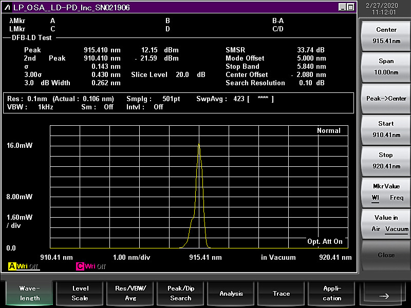
Centre Wavelength | λ | 910 | 915 | 920 | nm |
Spectral Width | Δλ | 0.6 | 0.8 | 2.0 | nm |
Threshold Current | Ith |
| 30 | 40 | mA |
Operating Current | Iop |
| 230 | 300 | mA |
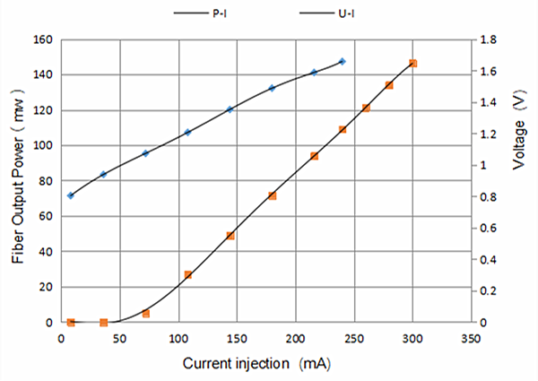
Fiber output Power | Pf | 70 | 100 | 150 | mW |
Wavelength Tuning VS Temp | Δλ/T |
|
| 0.01 | nm/°C |
Tracking Ratio(0.1Pop < Pf< Pop)1 | TR | 0.52 |
| 1.48 |
|
Tracking error2 | TE | -48 | - | +48 |
|
Monitor diode responsivity | IBF | 0.5 |
| 5 | uA/mW |
Thermistor resistance(Tset = 25°C)3 | Rth | 9.5 | - | 10.5 | KΩ |
PD Dark Current (VRD=5V) | Id |
|
| 0.1 | uA |
Extinction Ratio(PM VERSION) | PER | 17 | 20 |
| dB |
Coupled Fiber Type | HI1060 |
Forward Voltage | Vf |
| 1.8 | 2.6 | V |
Thermistor Resistance | RT | 9.5 | 10 | 10.5 | KΩ |
Thermistor Temp. Coefficient |
|
| -4.4 |
| %/°C |
Connector | None or FC/APC |
Thermistor Resistance |
|
1. The tracking ratio is a measure of the front-to-back tracking when the output power is varied. On a plot of optical power versus back-face photocurrent, a straight line is drawn between the minimum power (30 mW) and the operating power (Pop) points. The tracking ratio is defined as the ratio between measured optical power (shown as data points on the plot) to the value derived from the straight line.
2. The tracking error is defined as the normalized change of output power relative to Pf at 25°C, that is, (Pf – Pf_25)/Pf_25, over case temperature range of 0 to 75°C, at constant back face monitor current corresponding to the lowest back face monitor current at Pf= Pop of 0°C, 25°C, 75°C.
3. Datasheet for Calculating Temperature from the resistance of the Thermistor is available now. You can contact us for details.
Spectrum
L-I Curve
Package Size
Unit(mm)

Pin definition
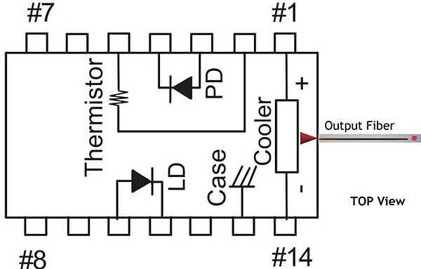
1 | Thermoelectric Cooler (+) | 8 | N/C |
2 | Thermistor | 9 | N/C |
3 | PD Monitor Anode (-) | 10 | laser Anode (+) |
4 | PD Monitor Cathode (+) | 11 | Laser Cathode (–) |
5 | Thermistor | 12 | N/C |
6 | N/C | 13 | Case Ground |
7 | N/C | 14 | Thermoelectric Cooler (–) |
HI 1060 Fiber Nominal Characteristics and Tolerances
Parameters | Specification |
Cut off wavelength | 920nm |
Max Attenuation | 2.1dB/km |
Cladding Diameter | 125um |
Coating Diameter | 250um |
Core Cladding Concentricity | ≤0.5um |
Mode Field diameter | 5.9um |
Absolute Maximum Ratings
Item | Symbol | Unit | Min | Typ | Max | Testing Condition |
Case Temperature | TOP | ℃ | -5 | 25 | 70 |
|
Chip Temperature | TLD | ℃ | +10 | 25 | 50 |
|
Operating Current | If-max | mA | 0 | 230 | 300 |
|
Forward Voltage | VR | V | 0.8 | 1.2 | 1.8 |
|
TEC Current | I TEC | A | - | 1.2 | 2.0 |
|
Tec Voltage | VTEC |
|
|
|
|
|
Axial Pull Force |
| N | - | - | 5N | 3x10s |
Side Pull Force |
| N | - | - | 2.5N | 3x10s |
Fiber Bend Radius |
|
| 16mm |
|
| - |
Reverse Voltage(LD) |
| V | - | - | 1.8 | C=100pF,R=1.5KΩ,HBM |
Reverse Voltage(PD) | VPD | V | - | - | 10 | C=100pF,R=1.5KΩ,HBM |
LD electrostatic Discharge | VESD-LD | V |
| - | 1000 |
|
PD electrostatic Discharge | VESD-PD | V |
| - | 500 |
|
PD Forward Current | IPF | mA |
| - | 10 |
|
Lead Soldering time |
| S |
| - | 10s | 300℃ |
Store Temperature | TSTG | ℃ | -40 | - | +85 | 2000hr |
Operating Temperature | TOP | ℃ |
| - |
|
|
Relative Humidity | RH |
| 5% |
| 95% |
|
Absolute maximum ratings are the maximum stresses that may be applied to the module for short periods of time without causing damage and are listed in Table 5.Stresses in excess of the absolute maximum ratings can cause permanent damage to the device. Exposure to absolute maximum ratings for extended periods of time or exposure to more than one absolute maximum rating simultaneously may adversely affect device reliability. Specifications may not necessarily be met under these conditions.
Application
● Pump Laser
● Dense wavelength division multiplexing (DWDM)
● EDFAs for small package designs
● High bit-rate, high channel-count EDFAs
● CATV distribution
Ordering Info
PL-FP-□□□□-☆-A8▽-XX
□□□□:Wavelength
405: 405nm
633: 633nm
680: 680nm
850: 850nm
915: 915nm
980: 980nm
*****
1550:1550nm
☆ :Output Power
A:50mW
B:100mW
C:150mW
▽:Wavelength Tolerance
1:±1nm
2:±2nm
XX: Fiber and Connector Type
SA=HI1060+ FC/APC
SP=HI1060+ FC/PC
PP=PM 980 + FC/PC
PA=PM980+ FC/APC
Labeling
Laser Safety
The LD-PD pump laser module emits hazardous invisible laser radiation.The pump laser module emits hazardous invisible laser radiation.Due to the small size of the pump module, the box packaging is labeled with the laser radiation hazard symbol and safety warning labels shown below
User Safety
Safety and Operating Considerations
The laser light emitted from this laser diode is invisible and may be harmful to the human eye. Avoid looking directly into the fiber when the device is in operation.
CAUTION: THE USE OF OPTICAL INSTRUMENTS WITH THIS PRODUCT INCREASES EYE HAZARD.
Operating the laser diode outside of its maximum ratings may cause device failure or a safety hazard. Power supplies used with this component cannot exceed maximum peak optical power.
CW laser diodes may be damaged by excessive drive current or switching transients. When using power supplies, the laser diode should be connected with the main power on and the output voltage at zero. The current should be increased slowly while monitoring the laser diode output power and the drive current. Careful attention to heatsinking and proper mounting of this device is required to ensure specified performance over its operating life. To maximize thermal transfer to the heatsink, the heatsink mounting surface must be flat to within .001inch and the mounting screws must be torqued down to 1.5 in/lb.
ESD PROTECTION—Electrostatic discharge (ESD) is the primary cause of unexpected laser diode failure. Take extreme precaution to prevent ESD. Use wrist straps, grounded work surfaces, and rigorous antistatic techniques when handling laser diodes.